ATL Transformers Academy
ATL design and deploy leading magnetics to the rail network and its principle contractors. We offer the highest specifications on the market while maintaining competitive pricing against alternative legacy technology. Our magnetics are approved for use by Network rail, Crossrail, London underground and are widely used to support Designers, Route asset manager, maintainers & Installers. As the preffered solution in rail ATL’s New generation of magnetics, eco-rail® is raising the bar on quality and performance, delivering unprecedented levels of weight/size reduction, ergonomics, Carbon reduction and safety.
ATL Academy Transformer Frequency
Transformer Frequency
Effect of frequency
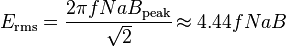
Transformer universal EMF equation
If the flux in the core is purely sinusoidal, the relationship for either winding between its rmsvoltageErms of the winding , and the supply frequency f, number of turns N, core cross-sectional area a and peak magnetic flux densityB is given by the universal EMF equation:
If the flux does not contain even harmonics the following equation can be used for half-cycle average voltage Eavg of any wave shape:

The time-derivative term in Faraday’s Law shows that the flux in the core is the integral with respect to time of the applied voltage. Hypothetically an ideal transformer would work with direct-current excitation, with the core flux increasing linearly with time. In practice, the flux would rise to the point where magnetic saturation of the core occurs, causing a huge increase in the magnetizing current and overheating the transformer. All practical transformers must therefore operate with alternating (or pulsed) current.
The EMF of a transformer at a given flux density increases with frequency. By operating at higher frequencies, transformers can be physically more compact because a given core is able to transfer more power without reaching saturation and fewer turns are needed to achieve the same impedance. However, properties such as core loss and conductor skin effect also increase with frequency. Aircraft and military equipment employ 400 Hz power supplies which reduce core and winding weight. Conversely, frequencies used for some railway electrification systems were much lower (e. g. 16.7 Hz and 25 Hz) than normal utility frequencies (50 – 60 Hz) for historical reasons concerned mainly with the limitations of early electric traction motors. As such, the transformers used to step down the high over-head line voltages (e.g. 15 kV) are much heavier for the same power rating than those designed only for the higher frequencies.
Operation of a transformer at its designed voltage but at a higher frequency than intended will lead to reduced magnetizing current; at lower frequency, the magnetizing current will increase. Operation of a transformer at other than its design frequency may require assessment of voltages, losses, and cooling to establish if safe operation is practical. For example, transformers may need to be equipped with “volts per hertz” over-excitation relays to protect the transformer from overvoltage at higher than rated frequency.
Knowledge of natural frequencies of transformer windings is of importance for the determination of the transient response of the windings to impulse and switching surge voltages.
Contact