ATL Transformers Academy
ATL design and deploy leading magnetics to the rail network and its principle contractors. We offer the highest specifications on the market while maintaining competitive pricing against alternative legacy technology. Our magnetics are approved for use by Network rail, Crossrail, London underground and are widely used to support Designers, Route asset manager, maintainers & Installers. As the preffered solution in rail ATL’s New generation of magnetics, eco-rail® is raising the bar on quality and performance, delivering unprecedented levels of weight/size reduction, ergonomics, Carbon reduction and safety.
ATL Academy Transformer Temperature & Insulation
Transformer Temperature & Insulation
ATL Transformer Design | |||||||||||||||||||||||||||||||
Our transformers are designed in a way that does not allow impermissible temperatures. The insulating materials have at least class E conforming to IEC 85, mostly class F (155 deg C) & class H (180 deg C) and on request even higher temperature classes. For the technical calculation, the temperature is calculated at 1,06 times the primary voltage in rated operation and in short-circuit case. | |||||||||||||||||||||||||||||||
Valid temp rise in standard operation conforming generally to BS EN61558 | |||||||||||||||||||||||||||||||
The transformers may not reach improper temperatures when used as intended. The conformance is checked according to BS EN 61558 .The transformers and chokes are connected to the rated input voltage and then they are stressed with an impedance, which would give the rated power at rated output voltage and at alternating currents with the rated power factor. Subsequently the input voltage is increased for 6%. After this voltage increase, the current circuit will not be changed. The test is repeated under no-load conditions.
Here: x = 234,5 for copper and: D temperature rise over t2, the highest temperature is D+t2 At the start of the test the windings need the be at the same temperature as the ambient temperature. For transformers with more than one input- or output winding or transformers that have a tapped input or output winding, the values with the highest temperature are considered. During the test, the temperature may not exceed the values given in table 1, if the transformer is operated with a rated ambient temperature (25°C or ta). | |||||||||||||||||||||||||||||||
Table 1:Highest temperature values at intended use | |||||||||||||||||||||||||||||||
| |||||||||||||||||||||||||||||||
Immediately after the test, the test item has to pass the voltage solidity, which is set in § 18.3 EN61558, though the test voltage is just connected between input and output current circuit. After the test, the electrical terminals may not be detached, the air and creepage distance may not be smaller than the values set in § 26 EN 61558-1; potting compound may not have phased out and overload protection may not have reacted. With extensive technical calculation (done with a computer software) of each transformer, we make sure, that the values in table 1 are not exceeded. A higher ambient temperature lowers the possible power of a transformer at given size. | |||||||||||||||||||||||||||||||
Max. warming at short-circuit and overload conform generally to BS EN61558 | |||||||||||||||||||||||||||||||
Table 2: Peak values of temperature in short-circuit and overload conditions | |||||||||||||||||||||||||||||||
| |||||||||||||||||||||||||||||||
Table 3: Values of T and k for fuses | |||||||||||||||||||||||||||||||
| |||||||||||||||||||||||||||||||
Insulation declaration conform to IEC 85 | |||||||||||||||||||||||||||||||
On request, you obtain an insulation declaration for each transformer. This includes information about the used insulation materials and their temperature class. | |||||||||||||||||||||||||||||||

Energy losses
An ideal transformer would have no energy losses, and would be 100% efficient. In practical transformers energy is dissipated in the windings, core, and surrounding structures. Larger transformers are generally more efficient, and those rated for electricity distribution usually perform better than 98%.
Experimental transformers using superconducting windings achieve efficiencies of 99.85%. The increase in efficiency from about 98 to 99.85% can save considerable energy, and hence money, in a large heavily-loaded transformer; the trade-off is in the additional initial and running cost of the superconducting design.
Losses in transformers (excluding associated circuitry) vary with load current, and may be expressed as “no-load” or “full-load” loss. Winding resistance dominates load losses, whereas hysteresis and eddy currents losses contribute to over 99% of the no-load loss. The no-load loss can be significant, so that even an idle transformer constitutes a drain on the electrical supply and a running cost; designing transformers for lower loss requires a larger core, good-quality silicon steel, or even amorphous steel, for the core, and thicker wire, increasing initial cost, so that there is a trade-off between initial cost and running cost. (Also see energy efficient transformer).
Transformer losses are divided into losses in the windings, termed copper loss, and those in the magnetic circuit, termed iron loss. Losses in the transformer arise from:
Winding resistance
Current flowing through the windings causes resistive heating of the conductors. At higher frequencies, skin effect and proximity effect create additional winding resistance and losses.
Hysteresis losses
Each time the magnetic field is reversed, a small amount of energy is lost due to hysteresis within the core. For a given core material, the loss is proportional to the frequency, and is a function of the peak flux density to which it is subjected.
Eddy currents
Ferromagnetic materials are also good conductors, and a core made from such a material also constitutes a single short-circuited turn throughout its entire length. Eddy currents therefore circulate within the core in a plane normal to the flux, and are responsible for resistive heating of the core material. The eddy current loss is a complex function of the square of supply frequency and inverse square of the material thickness. Eddy current losses can be reduced by making the core of a stack of plates electrically insulated from each other, rather than a solid block; all transformers operating at low frequencies use laminated or similar cores.
Magnetostriction
Magnetic flux in a ferromagnetic material, such as the core, causes it to physically expand and contract slightly with each cycle of the magnetic field, an effect known as magnetostriction. This produces the buzzing sound commonly associated with transformers, and can cause losses due to frictional heating. Leakage inductance is by itself largely lossless, since energy supplied to its magnetic fields is returned to the supply with the next half-cycle. However, any leakage flux that intercepts nearby conductive materials such as the transformer’s support structure will give rise to eddy currents and be converted to heat. There are also radiative losses due to the oscillating magnetic field, but these are usually small.
In addition to magnetostriction, the alternating magnetic field causes fluctuating forces between the primary and secondary windings. These incite vibrations within nearby metalwork, adding to the buzzing noise, and consuming a small amount of power.
Transformer Safety Standards
Low voltage Low power Transformer Standards EN61558-1
The old VDE 0550 and VDE 0551 transformer standards do not exist anymore. The previous EN 60742 (VDE 0551) transformer standards is outdated now also.
The up-to-date standards for transformers are now BS EN 61558 IEC 60076 (VDE 0570). Part 1 of the standard explains general requirements and tests. Part 2 lists special transformer types like safety isolating transformers (part 2-6) or SMPS transformers (part2-17) a separate standard, which still has a connection to part 1, for general requirements.
For larger power and voltage ranges IEC 60076 is consulted. Consisting of many parts this standard covers an array of transformer products from Dry type, Oil filled & Cast resin transformers.
UL5085 is typically adopted for UL approved transformers.
Transformer Screening
Definitions of ATL screens
Safety isolating earth screen
A metallic material (typically copper foil) between the primary and secondary windings offering isolation to ground between the two windings sometimes referred to as: Separation of dangerous active components by use of a conductive shield, which is located between the two parts and is connected to an external earth terminal.
Transformer Voltages
Low voltage
Low voltages are rated voltages that are not higher than 1000 V AC.
High voltage
High voltage is defined as a voltage, that is higher than a low voltage of 1000 V. The maximum we are able to produce at the moment is at 50 kV AC.
The AC high voltage output has the following special characteristics: One terminal is connected to earth (minus pole, green/yellow connector) and the other terminal is connected to the high voltage side (plus pole or “hot side”).
Current is calculated with the power I = P/U and is usually given in [mA].
The frequency is at 50 Hz sinusoidal. For special fields of application, frequencies can be higher. We already built transformers with 20 kV and 1000 Hz.
The insulation test primary – secondary is done with 120% of the high voltage value..
Line Reactors
ATL Transformers Line Reactors conform to EN 61558, EN 5008-1 and -2, EN 50082-1 and -2
Transformer Frequency
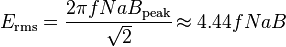
Transformer universal EMF equation
If the flux in the core is purely sinusoidal, the relationship for either winding between its rmsvoltage Erms of the winding , and the supply frequency f, number of turns N, core cross-sectional area a and peak magnetic flux densityB is given by the universal EMF equation.
Contact